|
© 1999-2001 Teledac Inc. Site Map Reach us |
NEW: See also I-Relay |
|
NETWORKING with IRISTEXT
Application note by Benoit Meilleur, Design Engineer Teledac Inc.
1. Abstract This paper describes the networking capabilities of Teledac's IRISTEXT video billboards. For each type of network (RS232, RS485, modem and ethernet), the topology, main characteristics and performance are discussed.
2. Introduction The simplest use of a video billboard system within an enterprise is a single editing and display unit to generate the video messages. These messages are transmitted to a network of television screens via a distribution network as an RF or base band signal. In this example, all TV screens carry the same information and a single Iristext unit is used to edit and display content.

In other cases, the TV screens are located in various locations and require different information according to the targeted audience. In this case, there must be at least as many display units as there are TV screens with distinct messages. When the operator is the same for all display channels, then a single edit station is required and forwards the information to various display units. If the information is entered at various points across the organization, then multiple edit stations must be used as each one serves a group of display units. These groups may be exclusive or shared by the other edit stations. In both cases, an interconnecting communication network between the edit and display video billboards must be constructed. 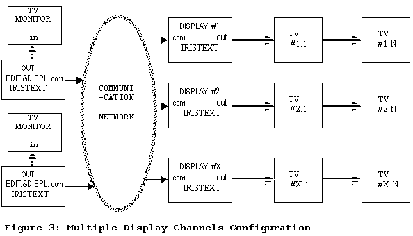
3. RS232 communication This communication standard is a point-to-point physical protocol used to connect 2 devices. Additional units may be connected by means of an intermediate switching device. This low-cost networking solution is efficient when the units are located close to each other as in an equipment rack. The maximum distance is approximately 100 feet.
3.1 2 units basic network This is the basic connection mode between 2 IRISTEXT units in near proximity, one being the master while the other may be an editing station or a display only unit. Our proprietary vector based graphic format maximizes the transfer rate by transmitting the graphic functions drawing the picture instead of the bitmap image. A typical update of a dozen pages is transferred in 5 to 10 seconds at 14400 baud. 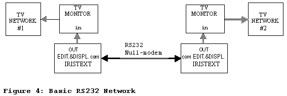
3.2 multiple units expansion 3.2.1 manual control With a passive switch box, any number of units can be connected to a master unit one at a time. The operator must manually switch the box to connect TxD and RxD signals. There is no need to have the I-NETWORK option since only 2 devices are connected at a time. However, no automatic transfer is possible. 3.2.2 automatic control with I-NETWORK option The I-NETWORK option allows each IRISTEXT unit to be uniquely defined and accessed on the network with a distinct identification number (or name since text labels are possible). It is software that must be installed in every EDIT unit. One of the EDIT stations will become a master to control the network. All other units will respond only when addressed by the master. Consequently, by using this option and a smart-switch (sometimes called RS232 port combiner), multiple display only units can be attached to a master unit. The automatic switch drives the data from the master port to all other ports. The first and only one to respond is routed solely to the master. The auto-switch senses the data signals to establish the connection to the master. 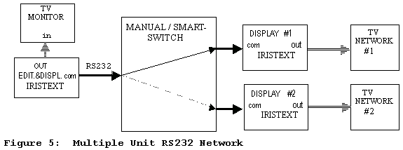
4. Modem network 4.1 without I-NETWORK option Each unit can be reached via the telephone network with the use of a modem on the communication port 1. Thus, each unit has its own telephone line and number. An operator can have any editing unit dial the phone number of any other unit and establish the communication for page transfer or remote display control. Between the modem and the IRISTEXT, the link is RS232 and the baud rate can be set from 300 to 14400 baud. 
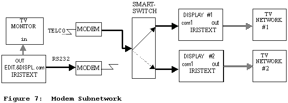
4.2 with I-NETWORKoption The I-NETWORK option allows one modem to access a group of IRISTEXT units as a subnetwork, thus sharing a single telephone line. In the case shown below, all units are display only and are connected through a smart switch or through RS232-to-RS485 converters on each unit. If one of those units is also an edit station, then the modem is attached to its communication port 1 and the local network is on the COM3 port. Any communication referred to a remote unit automatically generates the modem connection.
5. RS485 network (I-NETWORK option) A local network can be created by using RS232-to-RS485 converters on COM1 or COM3. These converters translate the unbalanced RS232 signal to a differential signal on a single twisted wire pair. The RS485 standard is more immune to electromagnetic interference and can drive longer cables. This hardware protocol permits multidrop networks. The converter drives the RS485 side only when it detects data on the RS232 TxD signal. Otherwise, it merely listens to the RS485 and brings any data from the RS485 pair to the RS232 RxD signal. This is possible because the software protocol is half-duplex, that is only one unit transmits data at a time. The differential nature of RS485 allows much greater cable length. With the appropriate cabling, a 4000-foot long network can be achieved. 
It is possible to take advantage of an existing Ethernet LAN to deliver the IRISTEXT data across edit and display units. An optional terminal server can be added to the video billboard communication port and encapsulate the IRISTEXT data into TCP/IP packets for 10BaseT or 10Base2 media. The transparent TELNET connection is automatically established at the beginning of the communication with the requested unit.
The terminal server can be configured locally at the IRISTEXT station or remotely from any PC on the network running appropriate software. The terminal server also supports gateway addressing to allow complete corporate WAN access. 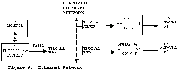
7. Conclusion The choice of a video billboard must include careful consideration of networking capabilities. Even when a single unit is anticipated, future expansion might require networking. So, the capabilities of the network should cover any need for a simple network such as point-to-point and the need for more elaborate networks such as ethernet LAN.
AN9906
|